Deep Dive into Water-Cooled Capacitors

Views : 511
Update time : 2025-08-07 10:52:38
Water Cooled Capacitor
Water-cooled capacitor is a kind of high power capacitor which is forced to dissipate heat by circulating water, specially designed for high power density, high frequency or continuous high current working condition, widely used in heavy industry, new energy, power electronics and other fields which need high efficient heat dissipation.
Electric capacitors are used as equipment in controllable or adjustable AC power systems with rated voltage not exceeding 3.6kV and frequency of 50kHz and below.

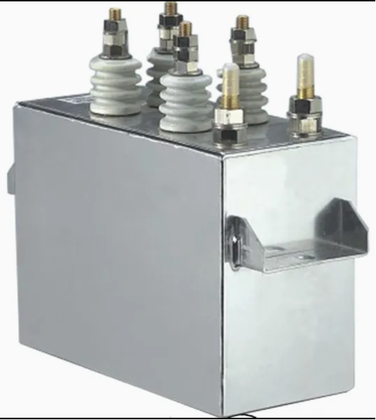
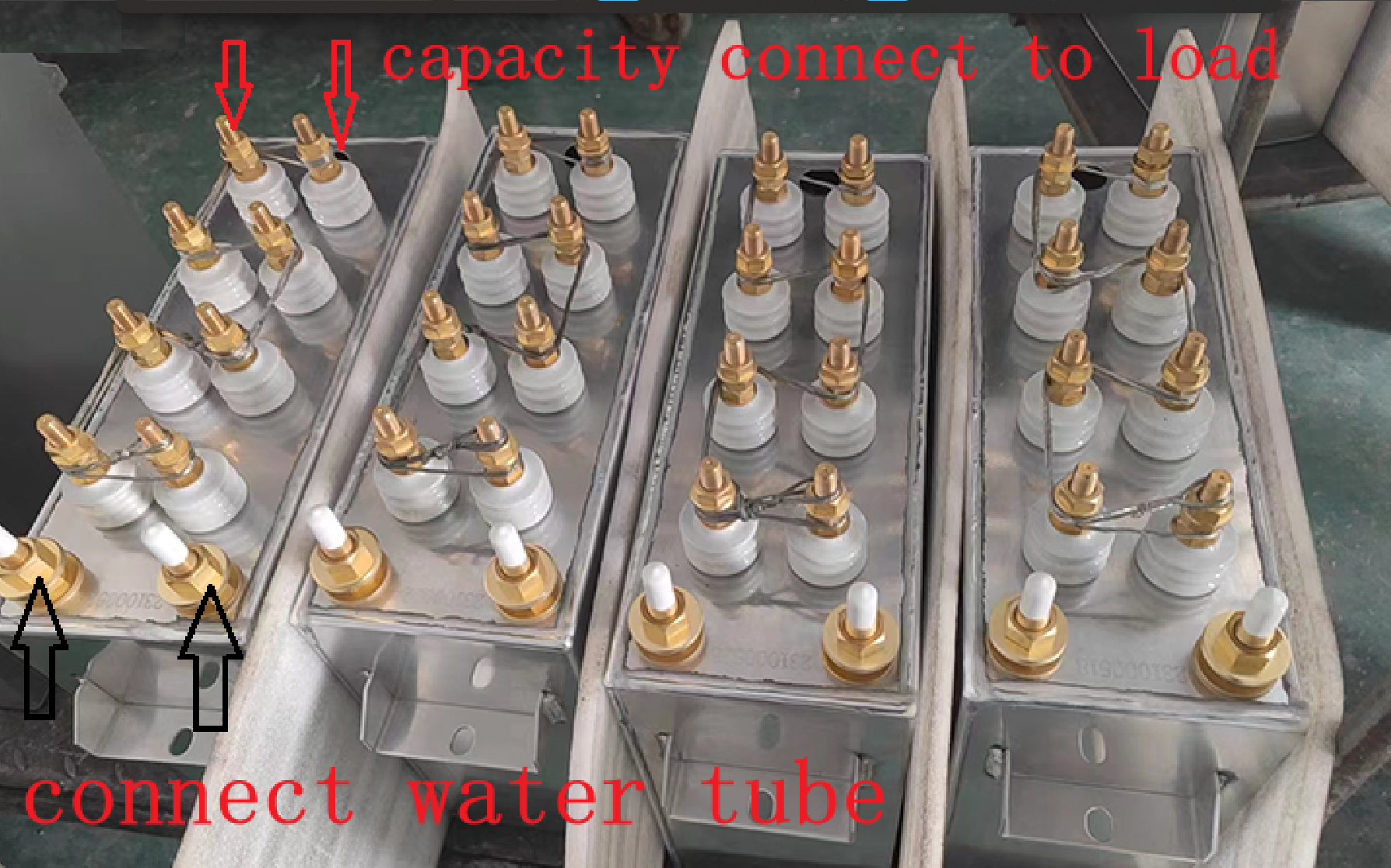
Structure and cooling principle of water-cooled capacitors
Structure:
Electrodes: High purity aluminum or copper foils to optimize conductivity and current-carrying capacity. Dielectrics: Polypropylene film (PP film), ceramic or mixed dielectrics for high temperature resistance and low losses. Cooling system: Cooling water channels: Built-in metal (aluminum/copper) or ceramic cooling plate with integrated circulating water circuit. Sealing interface: Inlet and outlet ports are made of corrosion-resistant materials (e.g. stainless steel), leak-proof design. Housing: Metal (aluminum shell common) or epoxy resin encapsulation, both mechanical strength and insulation.
Cooling principle:
Heat generated inside the capacitor due to high-frequency charging and discharging or high current is taken away by circulating water, and the heat exchange efficiency is more than 10 times that of air cooling. Typical water temperature control range: 20-40°C (to avoid condensation or boiling).


Technology of water-cooled capacitors

1. High Frequency Low Loss Design Low ESL (Equivalent Series Inductance): Optimize the internal structure (e.g. multiple parallel electrodes) to reduce energy loss at high frequency (1 kHz~1 MHz). Low ESR (Equivalent Series Resistance): High purity copper or aluminum foil electrodes are used to reduce current thermal effects. High-quality dielectric material: Polypropylene film (PP film): very low high-frequency loss (tanδ <0.0005), high-temperature resistant (≤120°C). Mica or ceramic: suitable for UHF (>1 MHz) scenarios. 
2. High-efficiency water-cooled heat dissipation system Direct cooling: direct contact between electrodes and copper water-cooled tubes for fast heat conduction. 3. Indirect Cooling: Aluminum shell with integrated water cooling plate for modular design. Sealing and leakage prevention: O-ring + epoxy resin encapsulation ensures long-term waterproofing.
3. High voltage resistance and long life rated voltage: 1 kV~20 kV, adapting to the resonant high voltage demand of electric heating equipment. 
4. Life Optimization: High temperature aging test (85°C/1000 hours), capacitance value deviation <5%.4. Cooling Water Circuit Design: Multi-circuit cooling to improve heat dissipation efficiency.
5. Insulation Oil Cooling: Part of the water-cooled capacitors adopt oil-immersed structure to enhance the insulation and heat dissipation.
6. Leak-proof and Corrosion-proof: Cooling system needs to avoid electrolytic corrosion and improve the reliability.

Role of Induction Heating & Melting Capacitors
1. High-efficiency conversion of electrical energy to thermal energy
In induction heating and dielectric heating, capacitors and inductors form LC resonant circuits, generating high-frequency alternating electromagnetic fields that heat metals (eddy current effect) or non-metals (dielectric loss).
Key Role:
Provide reactive power compensation to improve power factor (reduce line losses).
Match load impedance to maximize energy transfer efficiency.
2. Stabilizes high frequency currents
Suppresses voltage spikes in high-frequency circuits and protects power devices such as IGBTs/thyristors.
Reduces harmonic interference and improves system EMC performance.
3. Heat dissipation protection
Water cooling system can take away more than 90% of the heat generated, avoiding the failure of capacitors due to overheating (e.g. carbonization of PP film).


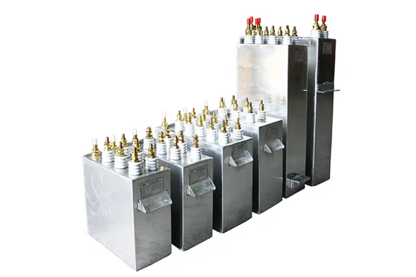
Uses of water-cooled capacitors
1. Induction heating equipment
2. Medium heating (high frequency electric field heating)
3. High power supply system
4. New Energy and Power Electronics

Usage Scenario
Metal melting furnace (such as medium frequency furnace, vacuum induction furnace)
Household/commercial induction furnaces (industrial-grade high-power models).
Heating power supply for semiconductor single crystal furnace.
Frequency conversion drive system for CNC machine tools, injection molding machines, cranes.
High-power servo motor controller (requires high-frequency low ESR capacitors).


Water Cooling Capacitor Drawings


Series resonant capacitors: mainly used in high frequency induction heating equipment to increase power factor
or improve circuit characteristic, it also used in melting and casting equipment.
RFM0.75- - 1000 - 1 S 
R=Electric heating 
F=Liquid medium code (diarylethane)
M=Solid medium code (polypropylene film)
1000=1000KvarRepresents rated capacity (kVar)
1= 1000hzRepresents rated frequency (kHz)
S=Endnote number (water-cooled)
RFM water cooling capacitor Electric heating Capacitor specification

Product Specification
型号规格    Model specifications 额定值 电容器外型尺寸 图号Drawing No
电压Voltage(V) 容量Capacity(Kvar) 频率Frequency(Hz) 电流Current(A) 电容Capacitor(μF) A B H kg
RFM0.75-1000-1S 750 1000 1000 1333.3    6*47.15 336 165 320 27    d
RFM0.75-1000-1S 750           1000 1000 1333.3    6*47.15 336 165 400 32    d
RFM0.75-1000-1S 750 1000 1000 1333.3    6*47.15 336 165 360 30    d
RFM0.75-1000-1S 750 1000 1000 1333.3    6*47.15 336 142 400 28    d
RFM0.75-1000-1.5S 750 1000 1500 1333.3    6*31.43 336 142 360 25    d
RFM0.75-1000-2S 750 1000 2000 1333.3    6*23.57 336 142 320 30    d
RFM0.75-1000-2.5S 750 1000 2500 1333.3    6*18.86 336 142 270 21    d
RFM0.75-1000-3S 750 1000 3000 1333.3    6*15.71 330 142 285 19    d
RFM0.75-1000-4S 750 1000 4000 1333.3    6*11.78 336 142 240 18    d
RFM0.75-1000-8S 750 1000 6000 1333.3    6*7.85 336 142 230 17    d
RFM0.75-1000-8S 750 1000 8000 1333.3    6*5.89 336 142 220 16    d
RFM0.75-1000-10S 750 1000 10000 1333.3    6*4.71 336 142 200 13    d
RFM0.75-1000-15S 750 1000 15000 1333.3    6*3.14 336 126 260 16    d
RFM 0.75-1000-20S 750 1000 20000 1333.3    6*2.35 336 126 220 16    d
RFM0.75-1000-30S 750 1000 30000 1333.3    6*1.57 336 120 285 17    d
RFM0.75-1000-40S 750 1000 40000 1333.3    6*1.17 336 126 320 18    d
RFM0.75-1500-1S 750 1500 1000 2000    8*53.05 440 165 360 32    e
RFM0.75-1500-1.5S 750 1500 1200 2000    8+35.36 440 165 425 32    e
RFM0.75-1500-2S 750 1500 2000 2000    8*26.52 336 170 380 30    e
RFM0.75-1500-2.5S 750 1500 2500 2000    8*21.22 336 142 340 25    e
RFM0.75-1500-4S 750 1500 4000 2000    8*13.26 336 142 330 25    e
RFM 0.75-1700-4S 750 1700 1000 2266.6    8*15.03 336 142 360 26    e
RFM0.75-2000-1S 750 2000 1000 2666.6    10*56.58 440 170 460 51    f
RFM0.75-2000-1S 750 2000 1000 2666.6    10*56.58 440 205 400 53    f
RFM0.75-2000-2.5S 750 2000 2500 2666.6    8*28.29 400 165 380 37    e
RFM0.75-2000-8S 750 2000 8000 2006.6    10*7.07 400 142 360 32    f
RFM 1.0-1000-0.5S 1000 1000 500 1000    6*53.05 440 165 360 39    d
RFM1.0-1000-1S 1000 1000 1500 1000    6*26.52 336 142 360 26    d
RFM1.0-2000-0.5S 1000 2000 500 2000    8*79.57 440 205 455 65    e
RFM 1.2-1000-0.5S 1200 1000 500 833.3    6*36.84 440 165 325 34    d
RFM 1.2-1000-1S 1000 1000 1000 833.3    4*27.63 336 142 300 25    c
RFM1.2-1000-2.5S 1200 1000 2500 833.3    4*11.00 336 142 285 19    c
RFM1.2-1200-0.7S 1200 1200 700 1666.6    6*31.57 400 165 350 35    d
RFM1.2-2000-0.5S 1200 2000 500 1666.6    8*55.26 440 205 425 48    e
RFM 1.2-2000-1S 1200 2000 1000 1606.6    8*27.63 440 165 360 37    e
RFM 1.2-2000-2.5S 1200 2000 2500 1666.6    6*14.73 336 142 300 20    d
RFM1.25-2000-1S 1250 2000 1000 1600    8*25.46 400 105 380 38    e
RFM1.25-3000-1S 1250 3000 1000 2400    8*38.19 345 170 600 49.5    e
RFM1.3-2000-0.5S 1300 2000 500 1538.4    8*47.08 440 205 435 48.5    e
RFM1.4-1000-0.5S 1400 1000 500 714.2    6*27.06 336 165 400 36    d
RFM1.4-2000-0.5S 1400 2000 500 1428.5    8*40.6 440 205 400 49    e
RFM1.4-2000-1S 1400 2000 1000 1428.5    8*20.3 440 165 360 37    e
RFM1.5-1000-1S 1500 1000 1000 666.6    6*11.78 336 142 340 22    d
RFM 1.5-1000-2.5S 1500 1000 2500 606.6    6*4.71 336 142 240 16    d  
RFM1.5-1000-8S 1500 1000 8000 666.6    6*1.47 336 126 220 14    d
RFM1.5-1500-1S 1500 1500 1000 1000    6*17.68 336 165 380 30    d
RFM1.5-2000-0.5S 1500 2000 500 1333.3    6*47.15 440 205 435 58    d
RFM1.5-2000-1S 1500 2000 1000 1333.3    6*23.57 400 165 360 33    d
RFM 1.5-2000-2.5S 1500 2000 2500 1333.3    6*9.43 336 142 400 26    d
RFM1.5-3000-1S 1500 3000 1000 2000    8*26.52 440 205 435 51    e
RFM 1.6-2000-0.5S 1600 2000 500 1250    6*4144 440 205 435 55    d
RFM 1.6-2000-1S 1600 2000 1000 1250    6*20.72 440 165 380 38    d
RFM1.7-1500-0.25S 1700 1500 250 8823    4*82.6 300 205 615 69    c
RFM1.8-3000-1S 1800 3000 1000 1000    8*18.42 440 205 400 44    e
RFM2.0-2000-0.5S 2000 2000 500 1000    6*26.52 440 205 435 56    d
RFM2.2-2000-0.5S 2200 2000 500 909    6*21.92 440 205 435 55    d
RFM2.5-2000-0.5S 2500 2000 500 800    6*16.97 440 205 420 42    d
RFM2.5-2000-1S 2500 2000 1000 800    8*6.36 400 170 400 36    e
RFM3.0-3000-0.5S 3000 3000 500 1000    6*17.68 440 205 595 67    d
RFM3.0-3000-1S 3000 3000 1000 1000    6*8.84 440 205 380 43    d
Whats/Wechat/Phone:008613757876329
Facebook:Wang Dewey


Related News
Read More >>
Inside a Transformer Insulation Material Factory: How Reliable Insulation Components Are Manufactured Inside a Transformer Insulation Material Factory: How Reliable Insulation Components Are Manufactured
May .21.2026
This article takes readers inside a professional transformer insulation material factory in China to explain how durable, standards-compliant insulation components are made. It covers the importance of insulation materials in transformers, lists commonly used parts such as DDP insulation paper, pressboard, and epoxy insulation, introduces automated CNC processing and modern workshop production, and details applications in both oil-immersed and dry-type transformers. The article also highlights OEM and custom manufacturing capabilities, showing the complete production system and quality control behind reliable transformer insulation solutions.
Insulation Coordination for Low-Voltage Switchgear: IEC 61439 Design Requirements Explained Insulation Coordination for Low-Voltage Switchgear: IEC 61439 Design Requirements Explained
May .16.2026
Our low-voltage switchgear assemblies are designed in accordance with IEC 61439 standards, providing reliable power distribution, protection, and control solutions for industrial and commercial applications.

With optimized insulation coordination design, the system ensures stable performance under demanding operating conditions, including high humidity, high temperature, and unstable power environments. The products feature safe clearance and creepage distances, high dielectric strength, and strong resistance to insulation aging and electrical faults.

Widely used in industrial plants, commercial buildings, renewable energy projects, and infrastructure systems, our switchgear solutions offer:

High operational reliability
Stable electrical performance
Flexible customization
Easy maintenance
Compliance with international IEC standards

We also provide OEM and project-based customization services to meet different market and application requirements.
What Is the Function of UPS Uninterruptible Power Supply? What Is the Function of UPS Uninterruptible Power Supply?
May .11.2026
We provide high-quality, reliable UPS solutions tailored to diverse industrial, commercial and infrastructure needs. Our product range includes online UPS systems, industrial UPS solutions, high-frequency and low-frequency UPS, as well as customized power protection configurations. Designed to prevent sudden shutdowns, stabilize voltage, protect sensitive equipment from power surges and support continuous operation, our UPS systems are widely used in data centers, manufacturing facilities, hospitals, telecommunications and more. Backed by professional engineering support and global application experience, we offer comprehensive technical assistance and product selection guidance to ensure your critical operations stay protected.
What Is UPS Uninterruptible Power Supply? Core Differences Between High-frequency UPS and Low-frequency UPS What Is UPS Uninterruptible Power Supply? Core Differences Between High-frequency UPS and Low-frequency UPS
May .06.2026
Our UPS systems are designed to provide continuous and stable power for critical equipment. With advanced technology and strict quality control, our products are widely used in data centers, factories, and infrastructure projects.

Key Features
True online double conversion technology
High efficiency and stable output
Wide input voltage range
Intelligent monitoring system
Support OEM & customization
Applications
Data centers
Industrial production lines
Hospitals
Telecom systems
Financial institutions
Available Options
High-frequency UPS (compact, energy-saving)
Low-frequency UPS (heavy-duty, high reliability)
Single-phase / Three-phase systems
Technical Range
Capacity: 1kVA – 500kVA
Voltage: 110V / 220V / 380V
Frequency: 50Hz / 60Hz